The Innovation First VEX line of robotic components consists of a wide range of structural, sensing, and motion actuating elements. All of these sensing and actuating components are driven by the one and only control component, the Vex Cortex.
The Vex Cortex is the controller, or the brains, for a VEX robot. The Vex Cortex sports an ARM processor for user programs, 8 12 bit analog inputs, 12 digital input output ports, 2 UART ports, a single I2C port, 8 3 wire RC servo motor compatible outputs, and 2 H-Bridge 2 wire DC motor driver ports.
Today we’re going to walk through the first part of a tear down of the Cortex controller. The reason we’re doing a tear down is that as nice as the Cortex is it suffers from at least one well known weakness, the built in H-Bridge motor driver ports are undersized and prone to burn out under normal use.
The 8 RC style motor drivers rely on external plug-in H-Bridge motor drivers. If a motors stalls or over currents the external bridge can burn out but it is easily replaced. If the built in H-Bridge drivers burn out the Cortex is permanently damaged. Innovation First, the makers of the VEX Robotics line, including the Cortex, will disavow all responsibility after the warranty period runs out. Even if, in my opinion, the weak design of the internal motor drivers is the root cause of the failure.
VEX Forum\Official Technical Support\Cortex started smoking
VEX Forum\Official Technical Support\Possible Cortex Motor Controller Burn-Out?
With the right tools the internal H-Bridges can be replaced and the Cortex brought back to full functionality. The repair of the motor drivers will be covered in another post.
Keep in mind that opening the Cortex probably voids your warranty, and modifying the Cortex surely makes it ineligible for competition. Given that caveat, here we go.
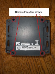
Disassembling the Cortex is straightforward, flip the Cortex on it’s back and you will see four philips tip screws, one in each corner.
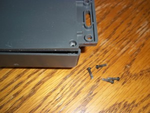
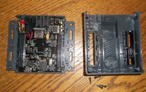
After removing the four screws gently pry apart the front and back covers. The circuit board will likely stay with the back of the housing with the front cover lifting off easily.
With the top off of the Cortex the main circuit board is exposed.
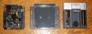
After removing the top gently pry the circuit board off of the bottom part of the housing. The circuit board is just wedged into tabs on the bottom of the housing and is not fixed in place.
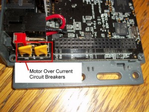
The Cortex has two thermal overload breakers inline with the motor control circuits. If the motors draw too much current the breakers overheat and reduce current to the motors, effectively putting the motors, and your robot, out of action until the breakers cool down. The breakers serve to protect the Cortex but pose a serious issue in a competition. The breakers take up to tens of minutes to cool down, effectively putting your robot out of the match you are in and potentially out of the next match as well depending on how fast and furious the matches are coming.
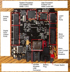
The major components of the Cortex are shown below.
The main system processor that controls the Cortex is an NXP LPC2458FET180.
From the NXP website for the LPC2458.
"The LPC2458 microcontroller is ideal for multi-purpose communication applications. It incorporates a 10/100 Ethernet Media Access Controller (MAC), a USB full-speed Device/Host/OTG Controller with 4 kB of endpoint RAM, four UARTs, two Controller Area Network (CAN) channels, an SPI interface, two Synchronous Serial Ports (SSP), three I²C interfaces, and an I²S interface. Supporting this collection of serial communications interfaces are the following feature components; an on-chip 4 MHz internal precision oscillator, 98 kB of total RAM consisting of 64 kB of local SRAM, 16 kB SRAM for Ethernet, 16 kB SRAM for general purpose DMA, 2 kB of battery powered SRAM, and an External Memory Controller (EMC). These features make this device optimally suited for communication gateways and protocol converters. Complementing the many serial communication controllers, versatile clocking capabilities, and memory features are various 32-bit timers, an improved 10-bit ADC, 10-bit DAC, two PWM units, four external interrupt pins, and up to 136 fast GPIO lines. The LPC2458 connects 64 of the GPIO pins to the hardware based Vector Interrupt Controller (VIC) that means these external inputs can generate edge-triggered interrupts"
The datasheet for the LPC2458 is here.
The system processor runs the Cortex system firmware, as opposed to the user uploaded robot control program. The system processor manages the wireless link and the bulk of the communication with the joystick.
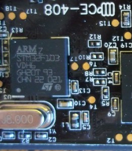
The user processor, the processor that runs the user uploaded code, is a STMicroelectronics STM32F103 ARM Cortex-M0 processor.
From the STM32F103 datasheet:
"Medium-density performance line ARM-based 32-bit MCU with 64 or 128 KB Flash, USB, CAN, 7 timers, 2 ADCs, 9 communication interfaces including up to 2 x I2C interfaces, up to 3 USARTs, up to 2 SPIs, a CAN interface, and a USB 2.0 full-speed interface."
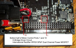
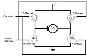
Four particularly interesting chips are the drivers for the internal H-Bridge motor drivers. The internal motor drivers form an H-Bridge consisting of an International Rectifier IRF8313PbF HEXFET Power MOSFET coupled with a Fairchild FDS4935BZ Dual 30 Volt P-Channel PowerTrench MOSFET.
The top half of the H-Bridge motor drivers are found on the bottom side of the circuit board.
The Top Half / Bottom Half nomenclature of the H-Bridge comes from the way H-Bridge circuits are typically drawn. The positive voltage to motor control FETs (P-Channel) are typically drawn above (nearer the top of the drawing) and the motor to ground control FETs (N-Channel) are typically drawn near the bottom of the drawing, top half, bottom half.
That pretty much wraps up the interesting chips. The VEX Cortex controller is not a particularly complex board but it is almost all surface mount components which makes it just this side of impossible for most robotics clubs to work on when it fails. At $250 USD each burning up a Cortex is not a cheap proposition.
In an upcoming post we will cover how to replace the motor driver FETs when motor ports 1 and 10 fail.

